Fish passes for hydropower weirs
Most run-of river hydropower weirs will need to be designed to allow fish and other aquatic species to migrate upstream and downstream. Upstream fish passage can be maintained through the construction of a fish pass.
Fish passes can be sub-divided into two main types:
- formal or technical fish pass
- easement or non-technical fish pass
What is the difference between a formal fish pass and an easement?
Formal fish passes are usually built to detailed hydraulic design standards that provide specific flow conditions for fish movement. They are often referred to as technical fish passes for this reason and should be designed by specialist environmental engineers. They require Formal Approval from Natural Resources Wales and are likely to be required for fish passage on migratory routes for salmon and sea trout or where access may be improved in the future as part of a river restoration scheme. Developers should refer to the Environment Agency Fish Pass Manual for design of formal fish passes.
You can download the Fish Pass Manual from the Institute of Fisheries Management website
A fish easement describes a non-technical type of fish pass that may not require Formal Approval .Whilst its purpose is still to provide fish passage over an in-river obstruction, the design of an easement tends to be less complex than a formal fish pass and may even include minor works such as a pre-barrage or retrofitting timber baulks to the face of a weir to improve flow conditions, rather than construction of a complete fish pass structure. The design of an easement will still need to be of a standard that meets the approval of our local Fisheries Officer.
An easement will be required on hydropower weirs that are beyond the upstream limits of salmon and sea trout migration but where upstream passage is required for resident trout and other local fish species. These sites tend to be in rivers and streams of smaller upland catchments and are typical of the locations for most small, high-head, run-of-river hydropower schemes. Our favoured type of easement for hydropower weirs is the nature-like rock ramp design which we describe in more detail later in this section. Easement design should be included in the engineering drawings for an impoundment licence application and will be assessed by our Fisheries specialists during the licence determination process.
It is also likely that there will be a need to provide upstream passage for eels at most hydropower weirs. Eels have different movement characteristics to fish and the flow conditions in fish passes may not be suitable for eels. In these cases, a separate eel pass may be required. Eel pass design is covered at the end of this section.
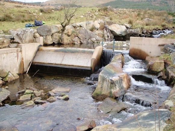
Provision for downstream fish passage will need to be made on all hydropower weirs. This should be achieved using a rectangular notch to pass the protected low flow and to ensure that fish can pass freely over both the screened overspill intake and residual flow sections of the weir in high flows, with plunge pool below both to prevent stranding and physical harm to fish.
When will a fish pass or easement need to be installed?
We are likely to require a fish pass or easement to be built when:
- a new impoundment is constructed
- an impoundment is rebuilt or reinstated over more than half the original length, or
- an existing impoundment is raised or otherwise altered or any other obstruction to the passage of salmon, migratory trout or other local fish species is created or increased.
We may require a developer to fund fish passage improvements as part of a scheme where improved fish passage is needed to meet local environmental objectives, even though the introduction of the hydropower scheme may not make existing fish passage worse.
Where an existing in-river structure (natural or man-made) is passable, a reduction in flow over it, caused by abstraction for hydropower, may reduce the efficiency of fish passage or the window of opportunity for fish to pass. Where this is the case the abstraction regime may need to be modified to retain adequate flows for fish passage. Alternatively, modifications such as lowering, removal or construction of easements may need to be made to the structures to maintain the existing level of performance.
Requirements for formal fish passes and easements - key principles
- Contact your local NRW Fisheries Officer to discuss fish pass requirements
- Include a formal, technical fish pass in your design if your scheme is on a known migration route for salmon and sea trout unless an alternative design has been agreed by NRW Fisheries Officers.
- Include a non-technical fish easement in your design if the impounding weir for your scheme cannot be reached by migratory salmon and sea trout unless NRW Fisheries Officers have advised that no fish pass is required.
- Refer to the Environment Agency Fish Pass Manual and commission an expert environmental engineer to design your formal fish pass
Apply for a Fish Pass Approval from NRW for a formal fish pass
General design principles for fish easements
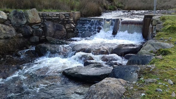
The head of a fish pass or easement should normally be positioned at the outflow of the low flow notch and residual flow weir. The head of the easement should be located on the main weir crest and be central to the main channel rather than on a side section.
We have described in Section 8 Design principles for hydropower weirs that where upstream fish passage is required, the low flow notch in the weir should have a base sloping downwards to the uppermost pool of the pass. The sloping base enables flow to pass through the notch and into the fish pass with an adherent nappe where the flow passing out of the notch is in continuous contact with the channel bed without any air gap below it. This provides better hydraulic conditions for fish to pass upstream against the direction of flow. The upstream dimensions of the low flow notch must be sized to discharge the protected low flow rate as specified on the abstraction licence.
The head of the fish pass should be designed to allow free flow through the low flow notch.
The combined width of the intake weir and fish pass or easement should be within the natural width of the river channel and avoid any channel widening.
Fish pass and easement flows
With small passes or easements, the protected low flow will usually provide the minimum flow for the pass to operate effectively with additional flow passing over the residual flow section of the weir. For larger passes a higher flow rate may be needed. Where this is the case the Hands-off Flow threshold will be raised to include both protected low flows and fish pass flows. The flow rate will be dependent on the type of pass and its design.
Outfalls from fish passes should be co-located with the next largest source of flow over the weir, such as the residual flow section to maximise the value of water available for attraction and passage of fish
Designing fish passes - key principles
- Position the head of the fish pass or easement to receive the outflow from the low flow notch and residual flow section of the weir.
- Ensure the head of the fish pass or easement is located on the main weir crest and not served by a side offtake.
- Slope the base of the low flow notch down to the pass or easement to improve flow conditions for upstream passage.
- Ensure flow in the head of the fish pass does not back up and affect discharge through the protected low flow notch.
- Design the fish pass or easement to fit within the natural channel width
- Ensure the downstream entrance to the fish pass or easement is co-located close to the residual flow to provide a strong attraction flow for fish.
- Contact our Fisheries Officers if you think that there may be a need to change the design of your fish easement during the construction process.
Nature-like rock ramp easement
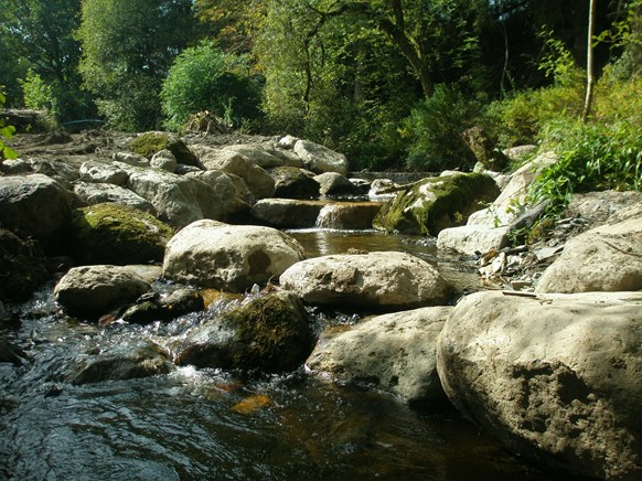
Our preferred design of easement for small hydropower schemes is the rock ramp. This creates a sloping channel from natural rocks that will provide the flow conditions for fish to pass upstream and over the main weir structure. The design of rock ramp type easements will vary according to the site. The main design principle is that it should replicate a naturally occurring rocky channel, step-pool or cascade feature, preferably like those present in adjacent river reaches.
Although rock ramps appear to be simple structures they must be carefully designed for them to be effective.
Rock ramps should be set within the main stream channel which must be stable. The ramp should be constructed with suitably sized natural stone so that it will remain stable under flood flow conditions and retain its original design. The size of stones should be consistent with those found naturally within the local river reach to avoid blockage and allow continued sediment conveyance. The stones used in the rock ramp should not be sourced from the river, bed or banks.
The ramp should be a rough, wide V shape with a clearly defined, central low flow channel. The central channel should be designed to have streaming flow through free gaps that maintain the depth and velocities of flow that are suitable for fish movement under low flow conditions. The low flow channel should be designed to take a meandering route down the ramp and avoid creating steep, uniform chutes. The central channel should be designed to convey the protected low flow at the rate set out in abstraction licence conditions.
Rock ramps should ideally have a gradient of no more than 10% (a slope where the change in elevation is 1 unit vertical for every 10 units horizontal). This may be difficult to achieve in steeper gradient streams typical of many micro-hydro sites. Where this is the case a steeper ramp gradient like that of the nearby channel may be used if the structure is well designed.
The ramp should be constructed with keystones securely set at intervals along the length and edges of the ramp. Key stones may be set as individual large stones or as a row across the ramp. These form important anchors to secure the rest of the ramp structure in place. A range of smaller sized rocks should be carefully placed between the key stones to form the ramp slope and construct the low flow channel. It is essential that the rock ramp does not leak and retains water in the constructed channel. It may be achieved through use of some concrete to secure keystones in place and block voids although placement of finer natural material such as gravels and sands in the pools and voids will also help to achieve this. A leaky ramp will increase the likelihood of piping failure, where seepage through the structure washes out fine material, potentially leading to movement or collapse.
Ideally rocky ramps should be based on an alternating sequence of steps and small pools. Any steps within the rock ramp should be set to a maximum of 200mm.
The outflow at the base of the ramp into the river channel should be designed to discharge through a constrained gap. This has the effect of concentrating outflow and provides a strong attraction flow for fish.
Rock ramp easements - key principles
- Use a rock ramp design where possible if an easement is required
- Replicate the characteristics of naturally occurring, local step-pool features
- Use natural stone to construct ramp (do not source material from the river bed or banks)
- Ensure the head of the ramp is located at the outflow of the low flow notch and residual flow section of the weir.
- Use appropriately sized key stones to provide stability under flood flows
- Build the ramp to an overall slope of 10% or gradient similar to that of the nearby river channel.
- Build the ramp to a rough, wide V shape cross section with meandering, central, low flow channel.
- Ensure the ramp does not leak – use a range of stone sizes and fill voids with fine sediment to retain flow in the constructed channel.
- Have a drop of no more than 200mm at steps in the ramp.
- Slope the base of the low flow notch on the weir to create an adherent nappe.
- Have a drop of no more than 150mm between the base of the low flow notch and the water level at the head of the easement.
- Discharge outflow at the base of the ramp through a narrowed gap to increase attraction flow.
Pre-barrages
Pre-barrages are used where upstream water levels need to be elevated within the channel downstream of the weir for the creation of a plunge pool or to improve flow conditions for fish to pass an in-river obstruction. A pre-barrage or several pre-barrages may be built by setting keystones across the river bed but ensuring that there is a central channel through which flow and sediment may pass. The keystones used in the pre-barrage should not be sourced from the river, bed or banks. One or more pre-barrages such as timber baulks may also be attached to the downstream face of existing concrete structures to increase water depths and improve passage over the structure.
Plunge pools for downstream fish passage
Weirs should be designed with plunge pools that allow downstream migrating fish to pass over the weir in river flow and to fall into a depth of water preventing physical harm or stranding.
The weir crest should have smooth or chamfered edges without any sharp metal or concrete upstands to allow free passage of fish over it during periods of higher flow. The top of masonry or concrete walls below the intake screen should be sloping and kept as narrow as possible to reduce risk of physical damage or stranding of fish passing over the screen.
Plunge pool depth must be a minimum of 300mm. Exit from the plunge pool should be through a notch of similar size to the low flow notch in the main weir and must be a minimum 150mm wide and 50mm deep.
Plunge pools should ideally be created from natural materials and must retain water. Use of boulders to create a pre-barrage is more sympathetic to river channel habitat and appearance than use of a formal reinforced cast concrete structure. Designers will need to consider access to the weir for screen cleaning as a plunge pool downstream of the intake section of the weir may make access for maintenance difficult. Any proposed changes to the river channel or bed including moving natural materials to create a pre-barrage or any other river engineering must be shown on technical drawings supporting a licence application.
Plunge pools can also act as stilling basins to dissipate flow energy downstream of a structure and help to control erosion.
Penstocks should be routed so that the pipeline does not create an obstruction in the river channel downstream of the intake weir and impede free downstream movement of fish.
Downstream fish passage and plunge pools - key principles
- Ensure that there are plunge pools below intake weirs
- Ensure the plunge pool depth is a minimum of 300mm deep.
- Ensure there is a pool outflow notch of minimum 150mm wide by 50 mm deep
- Use boulder stone pre-barrages to create plunge pools
- Ensure the plunge pool isn’t leaky and will always retain water
- Include pre-barrages in your technical drawings
- Avoid routing the penstock in the river channel below the intake weir
- Avoid flat surfaces, plinths or other in-river obstructions in the weir design that may impede free downstream movement of fish.
Eel passage
Populations of eels have fallen dramatically in recent years and they are now classed as an endangered species and have legal protection. Hydropower weirs can block migratory routes for eels and so must be designed to provide suitable upstream and downstream passage. The flow conditions in fish passes designed for salmon and trout are not normally suitable for eels. Separate eel passes will therefore be required on all new hydropower weirs or existing weirs modified for hydropower use unless our Fisheries Officers have advised that due to site conditions an eel pass is not required.
There are two main types of eel pass commercially available. These are:
- Brush type
- Boss type
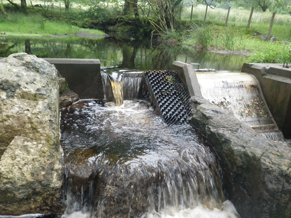
Brush substrate consists of plastic bristles set in a base tile. The bristle tiles are often either placed against a vertical face of the structure or enclosed within an independent channel or conduit. The boss type substrate consists of moulded protrusions from a base tile.
Arrangements for eel passage
Eel passes should ideally be located close to the bankside of any in-river structure. Boss tiles will need to be fastened on a slope to the front face of a weir while closed conduits for bristle type substrate may be located on the edges and vertical sides of structures and require a small flow through them using gravity or pumped discharge.To be fully effective in allowing upstream eel passage, passes should be placed so that they extend from downstream, low river water levels, up the weir face and over the weir crest.
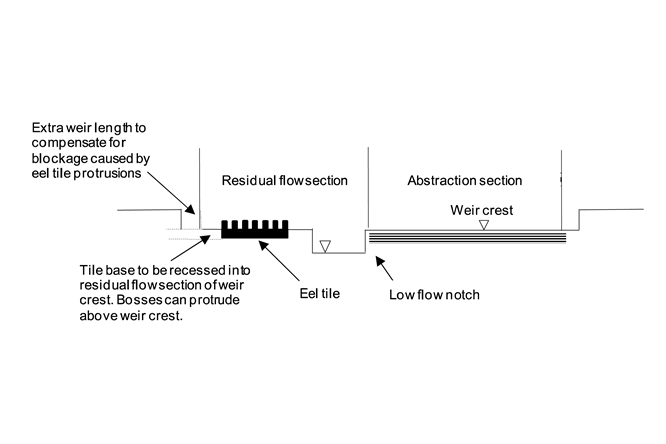
Boss type eel passes are less prone to blockage but will likely require installation on the main weir structure. They should not though be placed in low flow notches. This can affect flow rates through the notch as well as presenting an obstruction to downstream movement of fish and sediment.
A ramp of no greater than 45o slope may need to be constructed on the downstream face of the weir to provide a base on which to attach boss type eel tiles. The ramp should have small side upstands to retain flow within the pass.
For intake weirs with a protected low flow of 10 litres/second or less, boss type eel tiles may be placed on the face and crest of the residual flow section of the weir but with the tile base recessed into the weir structure. To account for the effect of the protruding bosses on weir crest flow, the residual flow section of the weir should be extended proportionally to equate to an extra 200mm length of crest for each 500mm of tile length (or equivalent) on the weir crest. Where the stream channel is narrow, and a full eel tile cannot easily be incorporated in the design, cut down eel tiles less than 500 mm wide may be used.
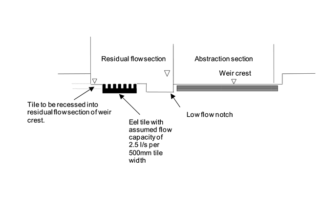
For weirs with a protected low flow of more than 10 litres per second, boss type eel tiles should be recessed in a separate eel pass channel on the weir crest so that the tops of the protrusions are level with the weir crest. A 500mm wide boss type eel tile set fully into the weir crest can be assumed to pass a flow of approximately 2.5 litres/second with partial blinding from leaves/woody debris. This design requirement will be separate and in addition to the protected low flow conditioned on the abstraction licence.
Eel passage - key principles
- Include an eel pass in your scheme design unless otherwise agreed by NRW Fisheries Officers.
- Locate the eel pass to the side of the in-river structure.
- Use bristle or boss type eel pass tiles/substrate.
- Ensure the eel pass extends from low flow river levels downstream of the weir and over the weir crest to ensure effective passage.
- Avoid placing the eel pass in the low flow notch.
- Set the eel pass into the residual flow section of the weir
- For schemes with a protected low flow of 10l/s or less recess the base of the eel pass tile into the weir crest but increase the width of residual flow weir by 200 mm per 500 mm width of eel tile.
- For schemes with a protected low flow greater than 10 l/s fully recess the eel pass tile into the weir crest.
- Include eel passes in your technical drawings